Table of Contents
Installation instructions Speedpuls
Foreword
The Speedpuls may only be installed by qualified personnel and at the user's own risk.
Neither the manufacturer nor the dealer can be held liable for defects resulting from incorrect installation or improper use.
Installation
- Removing the instrument panel
- Remove the cover of the Gala installation opening on the speedometer by means of predetermined breaking points, if available
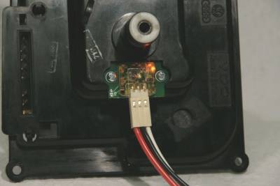
- Insert module and slide it towards the speedometer cable as far as it will go and screw it tight.
- Turn the speedometer shaft drive with a small screwdriver and listen for grinding noises. If necessary, place the enclosed washers under the module. Also, the LED should start flashing when turning.
- The tachometer needle should move back to its zero position on its own and without resistance.
- If this is not the case, the sensor tip can be corrected in the direction of the speedometer shaft by applying a slight amount of heat, e.g. a hair dryer. ATTENTION: DO NOT use hot air blowers or burners!
- Reassemble instrument carrier
Adjusting the output level
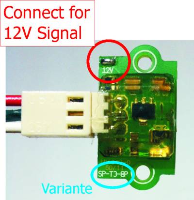
Optionally the output level can be adjusted to 12V (e.g. for TDI control units). Connect the open solder bridge for this purpose.
Connection
Assignment
| Color | Function |
|---|---|
| Red | Power supply 12V |
| Black | Ground |
| White | Signal |
Fuse
In itself the Speedpuls is short circuit proof. However, there is a possibility that the connection cable could trigger a short circuit due to a defect. Therefore, the Speedpuls must be protected by a fuse.
If the power supply of the Speedpuls is realized via a control unit, then it should be ensured that the control unit is fused accordingly.
No matter which voltage source is used, it must be ensured that a suitable fuse is used.
It is recommended to use a fuse at the power supply. Otherwise there is a risk of damaging the control unit in case of a short circuit. The fuse should be placed as close as possible to the voltage source.
The Speedpuls can also be connected with its power supply directly to the fuse box.
Suitable slots would be:
| Slot | Fuse | Terminal | Description |
|---|---|---|---|
| G3 | S12 (20A) | terminal X (ignition plus, but relieved at starter) | supply plus for air conditioning |
| G2 | S18 (10A) | terminal 15 (ignition plus) | supply plus for GRA (cruise control) |
Unsuitable voltage sources
Connecting the speed pulse directly to the battery (terminal 30) is unsuitable. Even if the current demand is in the mA range, this current is permanently drawn at terminal 30. Even if no signal is detected.
The speedpulse has no disconnection here.
Older documents
For historical reasons, the old documentation is still available here.
ATTENTION: These are no longer maintained!
Short manual:
Detailed installation instructions


