Table of Contents
Installation instructions speedometer board (Mark 3)
Preamble
With the majority of Vanagons/T25s are now over 30 years old, time is gnawing away at the speedo foils on many Vanagons/T25s. On the one hand, the foil can dissolve due to thermal and physical stress, on the other hand, problems in the electrical system (e.g. short circuit) can also cause defects in the foil.
This kit only replaces the speedometer film itself. It is not possible to solve defects in the vehicle electrics or the instruments themselves.
The board is not able to change or modify signals. In the case of an engine conversion, any existing tachometer must be used in accordance with the engine. A diesel needs the right diesel tachometer and a 5 cylinder petrol engine also needs the right 5 cylinder tachometer.
If the instruments are out of calibration, this board will not calibrate the instruments either. The displays can be adjusted using the repair guide or a specialist workshop.
This is the documentation for the replacement conductor foil for a VW Vanagon/T25 instrument cluster. Like all my projects, this one will be constantly evolving. Therefore, deviations of the technical status from the documentation may occur.
Disclaimer
The operation is intended for a vehicle in series condition (delivery condition). Installation may only be carried out by qualified personnel.
Before installation, also check that there are no other defects, such as short circuits, general faults in the electrics or other problems with the instruments. Especially if the original conductor foil already shows traces of overheated tracks, the electrical system must be checked before installation, otherwise damage to the circuit board and/or vehicle may occur.
ATTENTION!!!
Read this documentation carefully and completely. Failure to do so may result in damage to the circuit board and/or the vehicle.
Copyright
This documentation is the intellectual property of the author. Reproduction, even of extracts, is not permitted.
ABS parts from the 3D printer
All plastic parts were made from ABS with the help of a 3D printer. ABS has the enormous advantage that the parts remain stable even at higher temperatures. However, ABS has the disadvantage that it shrinks somewhat during processing. This disadvantage was taken into account during production. Therefore it can be technically conditioned that the parts must be partly again reworked (breaking out of supports or removing edges). Now and then it also happens that during printing the corners are somewhat rounded or the component is not completely flat. However, this does not affect the function.
Connectors
The plug connections on the board are designed to be protected against polarity reversal. Please never insert the plugs with force.
Required tools
The following tools are required.
A good pair of side cutters to shorten the LEDs. A wrench with SW7 or similar to loosen the screws from the indicators. A Phillips screwdriver to remove the old film. If your speedometer has already been repaired, then it could be that you need more tools. A lighter to shrink the heat shrink tubing over the connectors. Preparation of the board There are a few things to do before assembling the board.
Adapter Vanagon/T25 cluster connector and new board
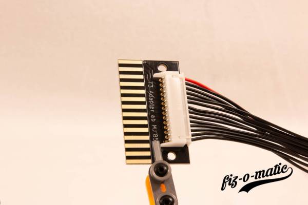
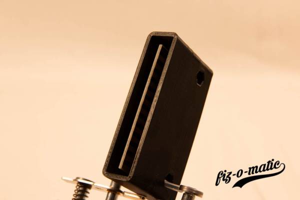
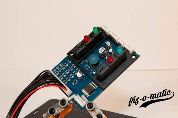
As the new conductor foil is simply plugged onto the instrument cluster, a separate adapter is required. This has its own housing which should protect against short circuits.
Due to the production process, it is possible that both boards are connected to each other. However, they have a predetermined breaking point whereby they can be broken apart quite easily.
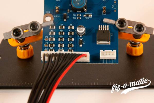
The plugs are designed to be protected against polarity reversal. There is a red cable for orientation. This should be plugged onto the adapter as shown in the picture. The housing can then be closed accordingly.
This board can then be installed in her case.
The LED’s
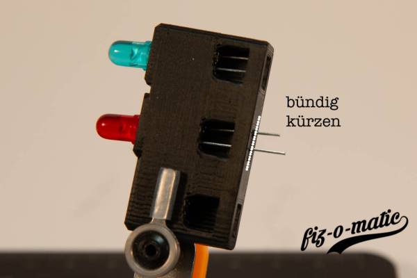
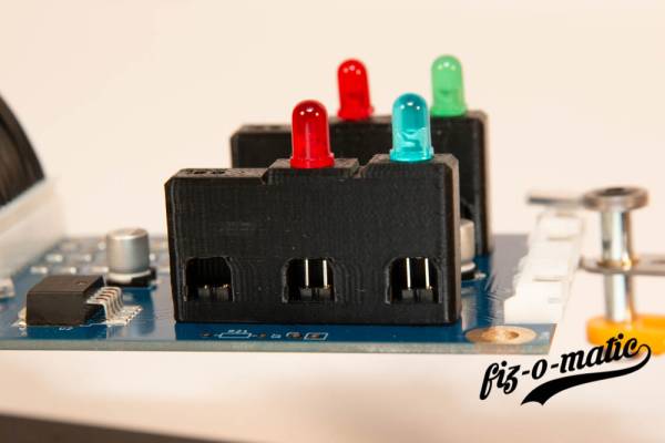
The LEDs still have to be shortened to the right length. Just put the LEDs through the spacer and cut them flush with a good side cutter. You can also mark the spot with a sharpie and then shorten it accordingly.
ATTENTION!!! The blue and green LEDs have the longest legs. Both red LEDs have the middle length and the yellow LED has the shortest legs.
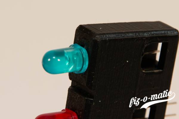
ATTENTION!!! All LED’s have a flattened side on the housing. You can also feel this well and it always comes up.
As soon as the LED’s are shortened they can be mounted.
Through the opening it can be checked that the LED’s are really hanging in the socket.
There is also an imprint on the board with the function designations. The LEDs must be used according to the following table.
| Function | Color |
|---|---|
| Turn signal | green |
| High beam | blue |
| Oil pressure control | red |
| Battery | red |
| Diesel | yellow |
Yellow high beam control
There was a time when VW installed a yellow high beam control. The yellow LED cannot be used for the high beam. This would not light up properly because the series resistor is too different.
Such speedometers should be converted to the blue LED.
The oil pressure control. Dynamic or static?
The dynamic oil pressure control compares different parameters. While earlier versions only check the minimum oil pressure, the dynamic oil pressure control can also evaluate the oil pressure at 2000 rpm.
As soon as you turn on the ignition, the oil pressure LED flashes if you have installed a dynamic oil pressure control. If the LED just lights up, you don’t have dynamic oil pressure control.
If the LED does not flash or light up, you can check if you have a connector on the back of the tachometer. In the case of a static oil pressure control, there is no plug.
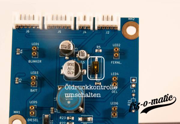
There is a small switch on the circuit board. With this you can switch off the dynamic oil pressure control.
To deactivate the dynamic oil pressure control and thus activate the static oil pressure control, the switch must be set to the “ON” position.
Fuel and Temperature display
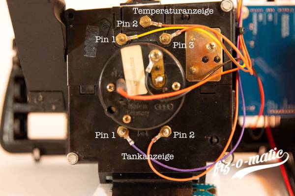
The fuel and temperature indicators have the following assignment.
| Pin | Color | Function |
|---|---|---|
| 1 | yellow | to the temperature sensor |
| 2 | brown | Ground |
| 3 | orange | 10V |
| 4 | purple | Signal from tank sensor |
| 5 | orange | 10V |
Depending on the variant of the instrument cluster, the display is located at the top or bottom. For instrument clusters without DZM or with analog clock, pin 1 is on the left side. If the display is on the lower half, then pin 1 is on the right side. Special attention must be paid to this during installation, otherwise malfunctions may occur.
Terminal assignment with Tachometer
Terminal assignment with analog clock or without clock
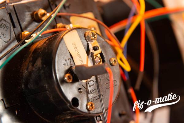
Since the air boxer does not have a temperature display, the superfluous cables must be protected against short circuits. With some skill and a very small screwdriver, the pins can be removed from the connector. Or you can also use a silk cutter to cut the wires close to the plug.
Tachometer
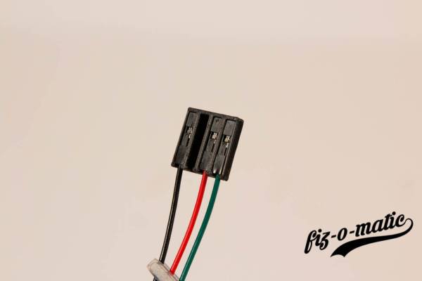
There is a 3 pin connector on the circuit board and the tachometer (DZM) has a 4 pin connector. With this one, however, the 2nd pin is not assigned.
The following assignment applies to all petrol engines:
| Pin (board) | Pin (DZM) | Color | Function |
|---|---|---|---|
| 1 | 1 | black | Ground |
| 2 | 3 | red | 12V |
| 3 | 4 | green | Speed signal |
There are two different assignments for diesel. Some diesel DZM are connected in the same way as the petrol engines. For other diesel DZMs there is the following assignment:
| Pin (board) | Pin (DZM) | Color | Function |
|---|---|---|---|
| 1 | 1 | green | Speed signal |
| 2 | 3 | black | Ground |
| 3 | 4 | red | +12V |
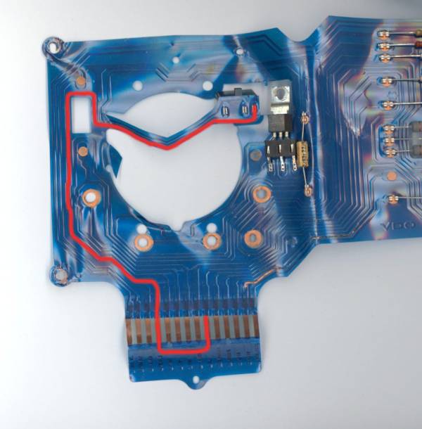
There are two ways to find out which variant you have. You can use a multimeter to measure where pin 9 of the instrument cluster connector goes. If this is no longer possible, one is then left with the option of following the track on the old film.
When it is clear which pinout is needed, then the connector can be prepared. All that is required is to press the individual plugs into the appropriate housing. Care should be taken to ensure that the plug is properly inserted. Otherwise you could damage the DZM during installation.
Dynamic oil pressure control
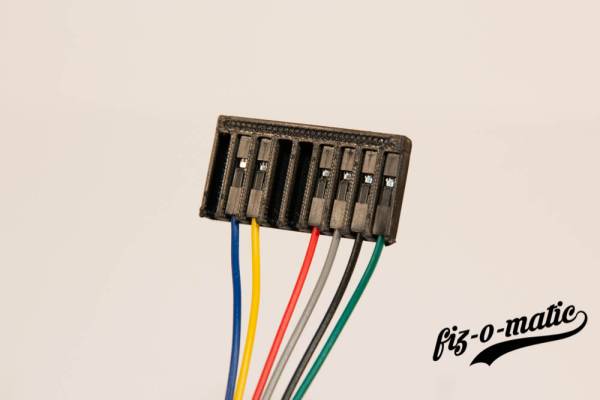
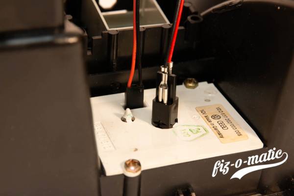
In the case of combination instruments with a dynamic oil pressure control, this must of course also be connected. The circuit board of the dynamic oil pressure control is located on the top of the speedometer housing. It is a 9-pin connector, with two pins of the connector unused. In the further description the pins are simply not counted for simplification.
| Pin (board) | Pin (oil pressure control) | Color | Function |
|---|---|---|---|
| 1 | 2 | blue | 0.3 bar sensor |
| 2 | 3 | yellow | 1.8 bar sensor |
| 3 | 6 | red | 12V |
| 4 | 7 | grey | LED |
| 5 | 8 | black | Ground |
| 6 | 9 | green | Speed signal |
Instrument lighting
For the upper illumination a 6 pin connector is provided on the board.
For the lighting a variant was chosen which allows a simple installation. For this there are extra lamp sockets for bulbs with T5 base.
As with the original speedo light, the socket also has a bayonet catch. The lamp is then locked with a quarter turn.
Since the upper space for the middle light is a bit cramped, it is necessary to bend the connectors a bit outwards. Otherwise, the connections will be crushed when the cover is installed. In addition, a piece of heat shrink tubing is placed on these connectors.
Clock
The clock (digital or analog) has a separate connector at the bottom corner of the board.
| Pin | Function |
|---|---|
| 1 | +12V Clock |
| 2 | Ground clock |
| 3 | +12V Lighting |
| 4 | Ground lighting |
The analog clock is also connected appropriately. In addition, a piece of heat shrink tubing is placed on the flat connector for the analog clock.
Mounting the circuit board
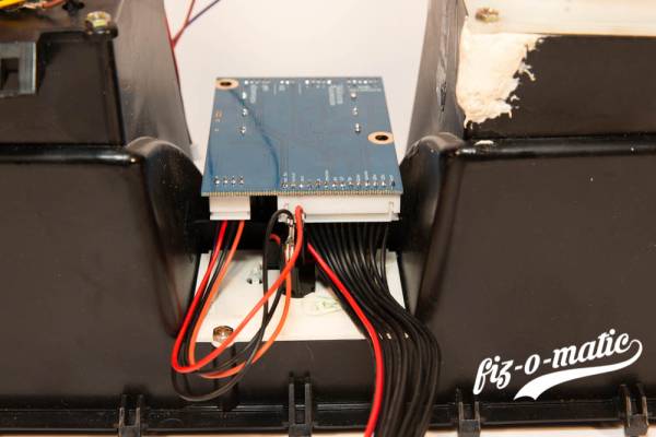
Before mounting the circuit board on the combination instrument, the blue cap of the high beam control must be removed.
Then the spacer and the cable are mounted. The spacer should already be mounted. Without it, unnecessary pressure is exerted on the circuit board and it can be damaged.
Afterwards the board can be put on and screwed on.
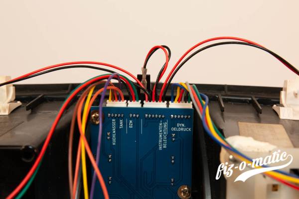
Now the cables can be connected to the board.
It is to be made certain that with the assembly, the speedometer light with the dynamic oil pressure control is confused. This can otherwise lead to damage.
The cables should still be fixed with the enclosed adhesive pads and cable ties.
Closing
Now the entire instrument cluster can be reinstalled.
Functional test
Before the first ride, everything must be checked for correct function. The following things should be emphasized above all:
- Oil pressure control or dyn. Oil pressure control
- Charge control
- Cooling water and low coolant indicator
- Fuel gauge
- Turn signal and high beam control
- Diesel preheating LED
Troubleshooting
Despite careful work during the installation of the tacho board, it can still happen that not everything works.
Error: Strange behaviour of the speedometer light and the displays when switching on the light.
Cause: There could be a defect in the electrical system. e.g. missing mass.
Solution: Please check or have checked if all signals are correctly connected to the connector for the instrument cluster. Above all, the ground must be applied correctly.
Error: The oil pressure control does not work.
The cause could be an incorrectly adjusted oil pressure control.
Solution: Check that the oil pressure control is set correctly. If you don’t have dynamic oil pressure control, then the switch must be set accordingly.
Error: The LEDs do not work partially or not at all.
Cause 1: Possibly the LEDs are installed the wrong way round.
Solution: Check the polarity of the LEDs according to the instructions.
Cause 2: Fault in the electrical system.
Solution: Please check or have checked if all signals are correctly connected to the connector for the instrument cluster.
Error: The charge control goes out already at idle speed.
Solution: VW has installed various series resistors for the excitation current of the alternator throughout the entire construction period. This may cause the behavior to change with the new board.
Since this is not a fault and does not affect the function of the alternator, there is no need to change anything here.
Error: I got LEDs for the speedometer light and they don’t work.
Cause: LEDs have a polarity. If this is not correct, then they do not shine.
Solution: Rotate the LEDs or, even better, use the bulbs provided for this purpose.
Error: I retrofitted a DZM and it doesn’t work or is wrong.
Cause: Although you can also retrofit a DZM wonderfully with the kit. But unfortunately you can’t just take any DZM. Since the board does not modify the signal, the DZM must already be suitable for the engine.
Solution: Check if the DZM is the right one and if it is OK.
Error: My problems are not solved despite the new board
Cause: If the old PCB was the cause of the problems, they should now be fixed. However, it may well be that the ladder foil was not the cause. Unfortunately, the new board cannot solve such problems either.
Solution: There will be nothing left but to check the electrical system.
Closing words
Finally, I wish you success and a lot of fun during assembly and always an accident-free and mishap-free ride.
